| View previous topic :: View next topic |
| Author |
Message |
jcstahl1


Joined: 22 Nov 2007
Posts: 207
Location: Johnstown, PA
|
 Posted: Fri Jun 20, 2008 2:53 am Post subject: The 360 LP Tilt Sensor Adjustment / Disable Guide - UPDATED Posted: Fri Jun 20, 2008 2:53 am Post subject: The 360 LP Tilt Sensor Adjustment / Disable Guide - UPDATED |
 |
|
First of all you need to open up your LP. Check BriGuy's modding 101 sticky.
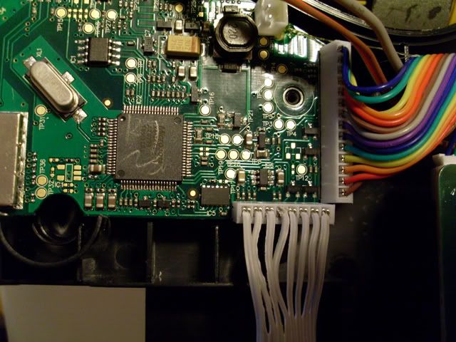
Here is a pic of the full 360 LP logic board. The area we will be working on is on the bottom of the board right beside the white plug with white wires that go to the fret connector.
Here you see the tilt sensor up close and personal.
And here is the data sheet that i found after 6 hours of searching.
http://www.freescale.com/files/sensors/doc/data_sheet/MMA7360L.pdf
Below the chip is the label IC5. The stock sensitivity (1.5g) is marked with the blue dots. To lower the sensitivity (6g) you need to unsolder the small jumper between the blue dots and move it to the gold contact pads where the red dots are. This is great for anyone who still wants to tilt for SP (!warning!: 6g is extremely hard to activate). This is very tricky as the diode and solder points are extremely small. A good soldering iron, a magnifying glass, tweezers, and steady hands are a must!! Not having the diode in either position is the same as the default setting. Now the green dots in the are where we are gonna disable the tilt sensor all together for those that want to use back or a alternate button/switch for SP (ie. foot pedal, etc.)
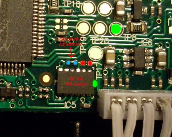
The tilt sensor connection is pin 7 on the side of the chip right beside the white plug and right below the letter T in TP17 and you can use any ground point on the board to jump it to. It is very hard to solder to pin 7 without a good iron, so that is HIGHLY recommened! I recommend TP8 because it is so close (it is a ground that is the same negative on the battery plug). You could also is a SPST switch to be able to turn the sensor on and off. This puts the sensor into sleep mode with will not let it activate until pin 7 is removed from ground. This will work on any revision of 360 LP (if there are any) as long as it has the same accelerometer.
I just got done testing this with my custom LP to SG conversion that had a seriously overactive SP activation. Now it doesn't activate till i hit select or my foot pedal.
| sscotth wrote: | Here are my pics of my guitar with the switch..
Seriously.. i'm so happy about this mod. I can still pre-tilt activate when i need to and I dont have to play with the neck to the ground anymore 
The Green wire goes to the other side of the board to the negative battery terminal and the white wire goes to TP17


 |
Link to sscotth's YouTube video showing a disabled tilt sensor in action
http://www.youtube.com/watch?v=w93aI6lrNR8
All information provided is from the in depth testing done by myself and sscotth. This may or may not apply to the PS3 LP's. If anyone can verify it with a PS3 LP, please PM me and I will add it to this guide.
Last edited by jcstahl1 on Fri Jun 27, 2008 2:20 pm; edited 5 times in total |
|
| Back to top |
|
 |
Dime333

Joined: 23 May 2008
Posts: 13
|
| Posted: Fri Jun 20, 2008 10:53 am Post subject: |
|
|
| I tried moving the resistor to the red position but now i have to slam the guitar up,down.left right like a fool to make star power activate. I think now it's too much unsensitive |
|
| Back to top |
|
|
jcstahl1
Joined: 22 Nov 2007
Posts: 207
Location: Johnstown, PA
|
| Posted: Fri Jun 20, 2008 1:39 pm Post subject: |
|
|
| Yes, I will say that moving the diode does make SP activation using tilt, a great bit harder. This is varied from guitar to guitar though. A few of the LP's i've done were extremely hard to deploy, while others weren't so bad (although still a great deal harder than OEM) |
|
| Back to top |
|
|
IWillKickU


Joined: 06 Dec 2007
Posts: 2830
Location: In the Undertow
|
| Posted: Fri Jun 20, 2008 2:14 pm Post subject: |
|
|
| This is a great guide, jcstahl. You get a double thumbs up for not only figuring this out, but making such an accessible guide for it. |
|
| Back to top |
|
|
BriGuy 


Joined: 04 Mar 2006
Posts: 1894
Location: Boston
|
| Posted: Fri Jun 20, 2008 3:34 pm Post subject: |
|
|
I would recommend that anyone having problems with their LP tilt sensor to first disable this accelerometer and then install another tilt sensor and wire it to the select button.
Check out this thread for details about replacement tilt sensors:
http://rockband.scorehero.com/forum/viewtopic.php?t=5132
Thanks again for this tutorial. Excellent work!
_________________
|
|
| Back to top |
|
|
esoteric311
Joined: 22 Jun 2008
Posts: 13
|
| Posted: Sun Jun 22, 2008 4:59 pm Post subject: |
|
|
| i tried to disable, i soldered tp17 to tp8 and the result i get is that im not able to power up my lespaul. once i removed the solder from tp8 it fired right up? any idea on this. im about to toss this thing out the window over here. :-( |
|
| Back to top |
|
|
jcstahl1
Joined: 22 Nov 2007
Posts: 207
Location: Johnstown, PA
|
| Posted: Sun Jun 22, 2008 5:29 pm Post subject: |
|
|
| hmm, that's strange. works great on mine. well just jumper TP17 to the negative at the battery connector on the back side of the board. |
|
| Back to top |
|
|
esoteric311
Joined: 22 Jun 2008
Posts: 13
|
| Posted: Sun Jun 22, 2008 5:41 pm Post subject: |
|
|
can you be a little more specific? are you saying to solder tp17 to the back side of the white connector where the battery line connects? and if so which is negative, red or black? thanks.
edit: ok so i took the board out and it was marked - and + when i ran a lead from tp17 to the negative as soon as i make contact the unit powers off. when i remove the lead it comes back on, is it possible that it isnt tp17 on my lp, perhaps something has changed? |
|
| Back to top |
|
|
esoteric311
Joined: 22 Jun 2008
Posts: 13
|
|
| Back to top |
|
|
sscotth

Joined: 25 Jul 2007
Posts: 519
Location: Cartagena
|
| Posted: Mon Jun 23, 2008 9:04 pm Post subject: |
|
|
The blue circles represent alternatives to TP17. TP17 just happens to be the largest and most easily soldered.
You can solder TP17 to any ground.
I used the negative battery terminal on the other side of the board |
|
| Back to top |
|
|
esoteric311
Joined: 22 Jun 2008
Posts: 13
|
| Posted: Mon Jun 23, 2008 10:01 pm Post subject: |
|
|
| when i connect my tp17 to the negative batt terminal, my lights ( on the xbox button) flicker and get very dim, any idea what is casuing that? ive never soldered it to them at the same time casue i didnt like the way the lights dimmed, i figured i did something wrong. |
|
| Back to top |
|
|
esoteric311
Joined: 22 Jun 2008
Posts: 13
|
| Posted: Mon Jun 23, 2008 10:40 pm Post subject: |
|
|
| jcstahl1 , scotch, success. Just for you guys to keep you up to date on things, when i soldered from tp17 to the negative battery terminal, the guitar will not power on. im using one of the smaller clue circle contact points. I just purchased this guitar on june 23 08. perhaps we have a new revision here. |
|
| Back to top |
|
|
jcstahl1
Joined: 22 Nov 2007
Posts: 207
Location: Johnstown, PA
|
| Posted: Tue Jun 24, 2008 1:10 am Post subject: |
|
|
| UPDATED with new deactivation points |
|
| Back to top |
|
|
sscotth
Joined: 25 Jul 2007
Posts: 519
Location: Cartagena
|
| Posted: Tue Jun 24, 2008 6:16 am Post subject: |
|
|
i didnt test pin 7 on the side of the chip so nice that you found that.
you may want to link my pic with the blue circles showing additional points that can be grounded.
I'll be getting a new guitar soon so i'll updated on the TP17 issue. |
|
| Back to top |
|
|
Dime333
Joined: 23 May 2008
Posts: 13
|
| Posted: Tue Jun 24, 2008 8:07 am Post subject: |
|
|
| Oh 1 thing...to make 6g work you don't need to resold the resistor but u can only jumper the 2 red points together with some soldering iron (remove the resistor from the 1.5g position first). Same thing if you want to go back with 1.5g. |
|
| Back to top |
|
|
|